Crash: Design and development
The project work was divided into three categories: hardware interfacing, collision detection, and wireless communication. Each team member assumed one category as his primary focus and worked in parallel with the others. Following component research and system architecture design, each component was individually tested for proper functionality. Components were then added incrementally to the system for interoperability verification. Once the completed system architecture was confirmed to work in a prototyping environment, the modules were permanently assembled and soldered. Collision detection and wireless communication algorithms were then developed while vehicle prototypes were constructed. Lastly, the completed CRaSH devices were affixed to vehicle prototypes for the purposes of measuring, testing, and demonstration.
Components
The Arduino Mega 2560 was used as the processing unit for two primary reasons: a generous number of input/output pins and larger memory capacity. Because the project relied on numerous external support libraries, the smaller and inexpensive Arduino Uno was deemed inadequate with only 2k bytes SRAM. In order to avoid stack/heap collisions, the Mega was ultimately selected as the system microprocessor.
The following list summarizes components and their applications:
- DS1307 real-time-clock (RTC) for recording the time of collision.
- LSM303 accelerometer for detecting collisions.
- XBee S1 radio for wireless V2V communication.
- SD card reader/writer for vehicle data storage.
- Lithium ion polymer battery for system power.
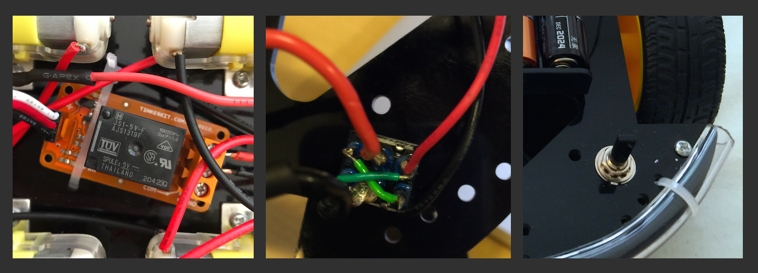
Wiring diagrams and photos of the project components are pictured below.


System architecture (left) and completed build (right).
vehicle prototype
Each vehicle kit shipped with four DC motors, a chassis, and a battery pack. Due to their primitive functionality, the vehicle prototypes were outfitted with additional features. A DPDT center-off toggle switch was used to control the vehicle (forward, reverse, on/off). A SPDT relay module was used to stop the motors upon collision. Lastly, an RGB LED was included to visually identify the following system states: standby, collision, sending data, and receiving data. A photo gallery of these features is provided below.


collision detection
Collisions were detected using the LSM303 accelerometer. A vehicle in motion produces near-zero values from the accelerometer, whereas a collision results in a spike in acceleration. The system remains in a collision-monitoring loop until a threshold is exceeded and a communication routine is called. The challenges in this approach were preventing false readings on vehicle starts and determining a proper threshold that accurately identifies a collision with another vehicle. A solution to the former was achieved by using sentinel checks/resets throughout the collision-monitoring routine. Performing a series of repeated collisions and observing accelerometer readings addressed the latter problem.
wireless communication
In facilitating a V2V communication system, we negotiated a compromise between a fully robust ad-hoc network and the native features of XBee radios. By default, XBee radios are configured to support networks arbitrated by a coordinator node. However, collisions are dynamic and unpredictable, so predetermination of a coordinator was not feasible. Our solution was to decentralize the XBee network with each radio sharing a generic destination address. Because the radios cannot simultaneously send and receive, it was also necessary to develop our own arbitration scheme that prevented ‘cross-talk’ between radios. We addressed this lack of arbitration by developing a ‘random back-off’ algorithm pictured below.
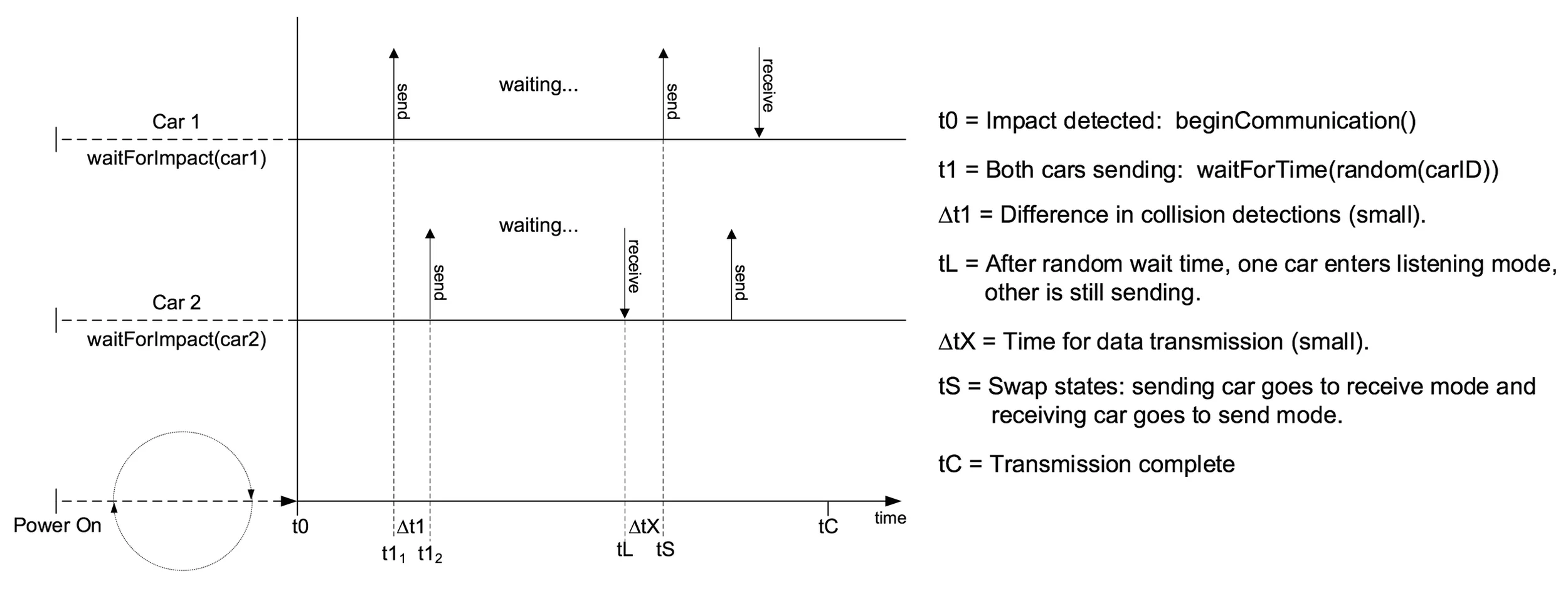
Random back-off algorithm for arbitrating V2V communication.